
Reverse Engineering Yaesu FT-70D Firmware Encryption
Table of Contents
This article dives into my full methodology for reverse engineering the tool mentioned in this article. It's a bit longer but is intended to be accessible to folks who aren't necessarily advanced reverse-engineers.
Click on any of the images to view at its original resolution.
# Background
Ham radios are a fun way of learning how the radio spectrum works, and more importantly: they're embedded devices that may run weird chips/firmware! I got curious how easy it'd be to hack my Yaesu FT-70D, so I started doing some research. The only existing resource I could find for Yaesu radios was someone who posted about custom firmware for their Yaesu FT1DR.
The Reddit poster mentioned that if you go through the firmware update process via USB, the radio exposes its Renesas H8SX microcontroller and can have its flash modified using the Renesas SDK. This was a great start and looked promising, but the SDK wasn't trivial to configure and I wasn't sure if it could even dump the firmware... so I didn't use it for very long.
# Other Avenues
Yaesu provides a Windows application on their website that can be used to update a radio's firmware over USB:
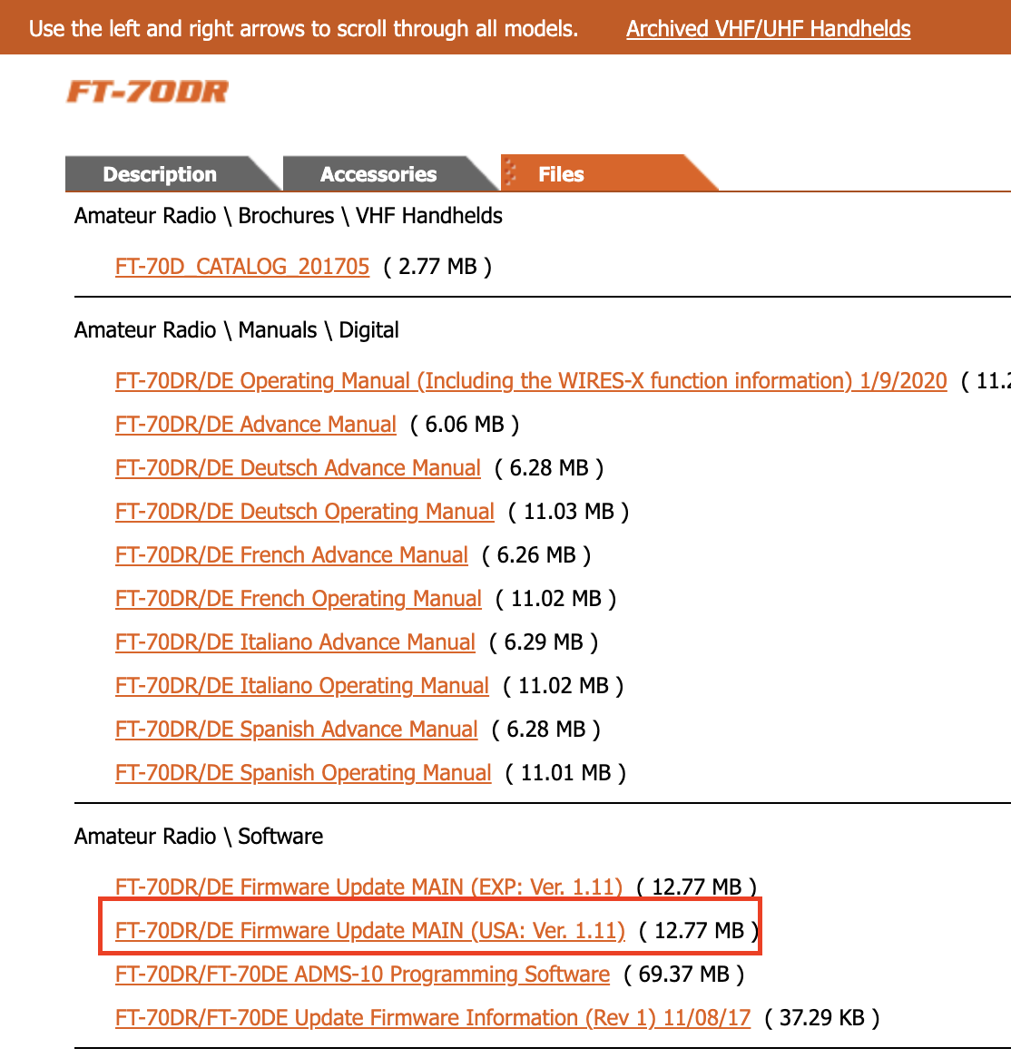
The zip contains the following files:
1.2 MB  Wed Nov  8 14:34:38 2017  FT-70D_ver111(USA).exe
682 KB  Tue Nov 14 00:00:00 2017  FT-70DR_DE_Firmware_Update_Information_ENG_1711-B.pdf
8 MB  Mon Apr 23 00:00:00 2018  FT-70DR_DE_MAIN_Firmware_Ver_Up_Manual_ENG_1804-B.pdf
3.2 MB  Fri Jan  6 17:54:44 2012  HMSEUSBDRIVER.exe
160 KB  Sat Sep 17 15:14:16 2011  RComms.dll
61 KB  Tue Oct 23 17:02:08 2012  RFP_USB_VB.dll
1.7 MB  Fri Mar 29 11:54:02 2013  vcredist_x86.exe
I'm going to assume that the file specific to the FT-70D, "FT-70D_ver111(USA).exe", will likely contain our firmware image. A PE file (.exe) can contain binary resources in the .rsrc section -- let's see what this file contains using XPEViewer:
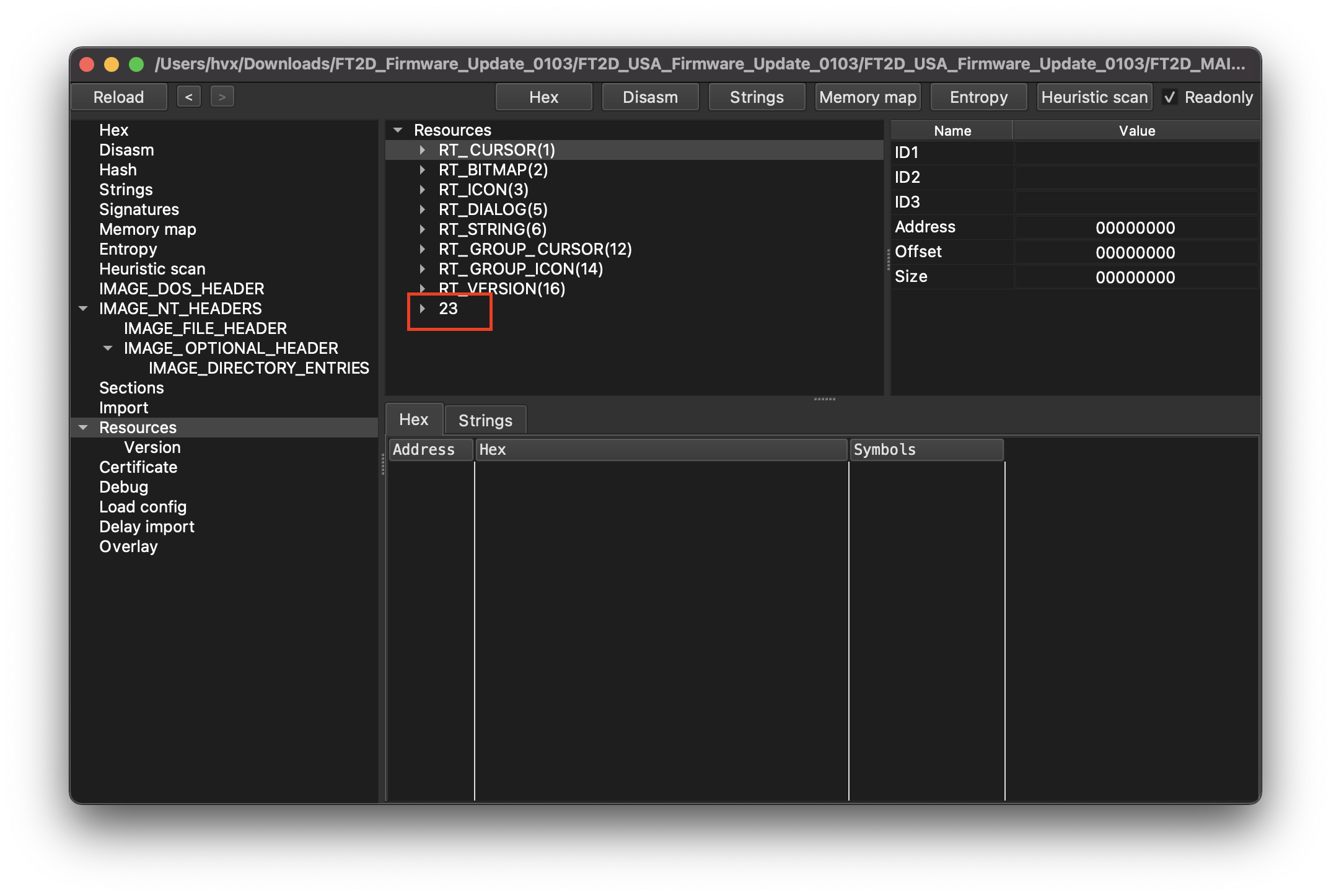
Resources fit into one of many different resource types, but a firmware image would likely be put into a custom type. What's this last entry, "23"? Expanding that node we have a couple of interesting items:
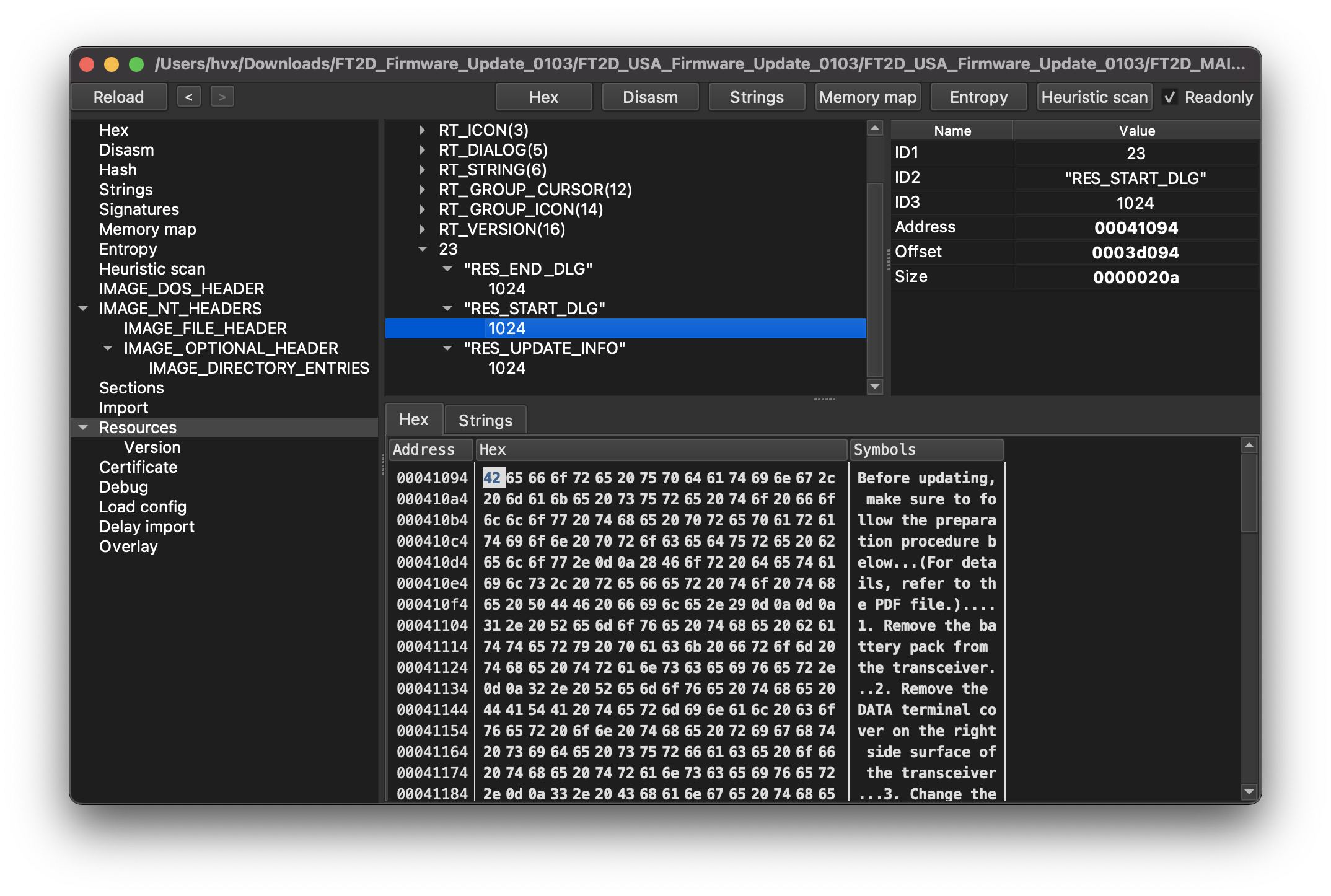
RES_START_DIALOG is a custom string the updater shows when preparing an update, so we're in the right area!
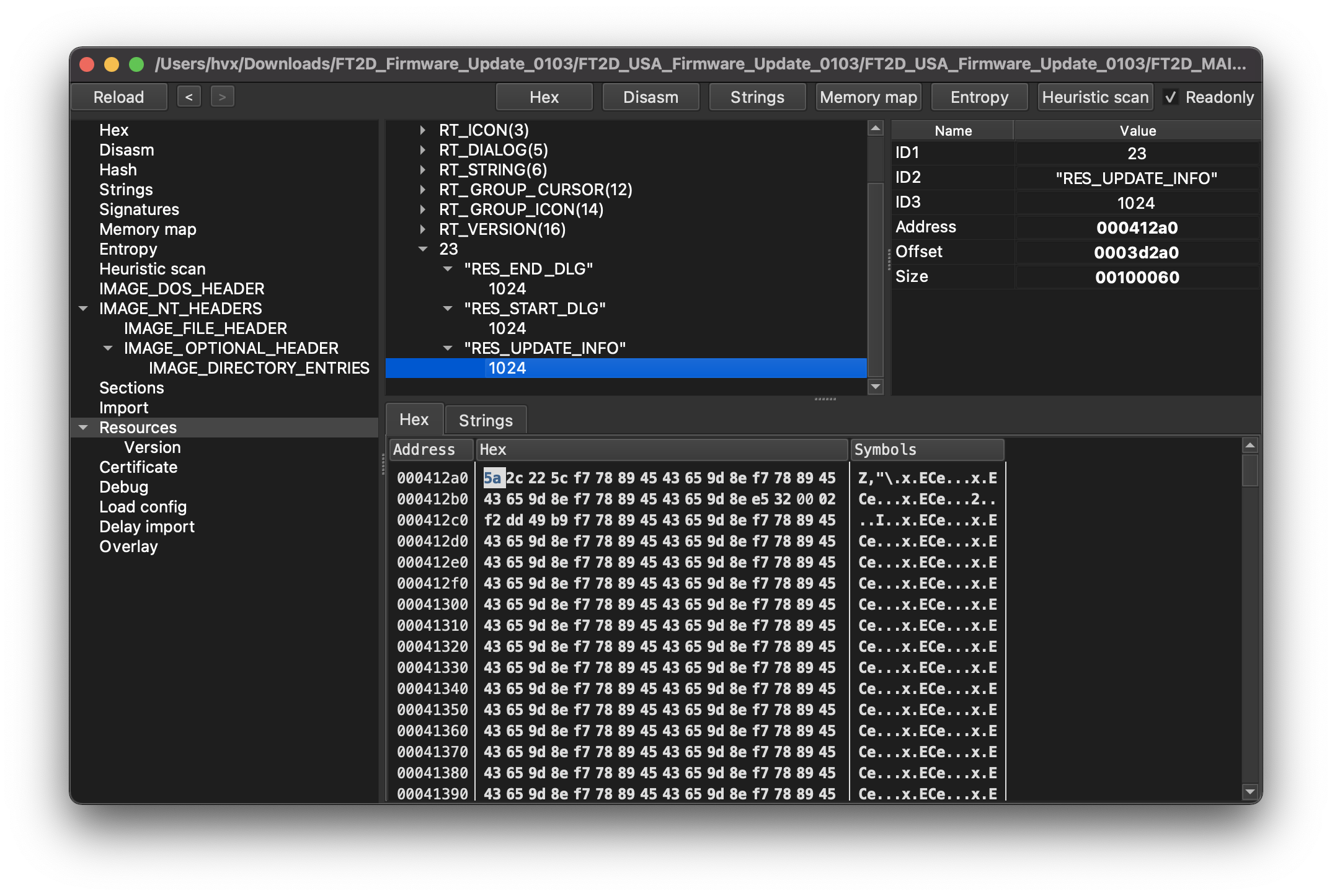
RES_UPDATE_INFO looks like just binary data -- perhaps this is our firmware image? Unfortunately looking at the "Strings" tab in XPEViewer or running the strings utility over this data doesn't yield anything legible. The firmware image is likely encrypted.
# Reverse Engineering the Binary
Let's load the update utility into our disassembler of choice to figure out how the data is encrypted. I'll be using IDA Pro, but Ghidra (free!), radare2 (free!), or Binary Ninja are all great alternatives. Where possible in this article I'll try to show my rewritten code in C since it'll be a closer match to the decompiler and machine code output.
A good starting point is the the string we saw above, RES_UPDATE_INFO. Windows applications load resources by calling one of the FindResource* APIs. FindResourceA has the following parameters:
HMODULE, a handle to the module to look for the resource in.lpName, the resource name.lpType, the resource type.
In our disassembler we can find references to the RES_UPDATE_INFO string and look for calls to FindResourceA with this string as an argument in the lpName position.

We find a match in a function which happens to find/load all of these custom resources under type 23.
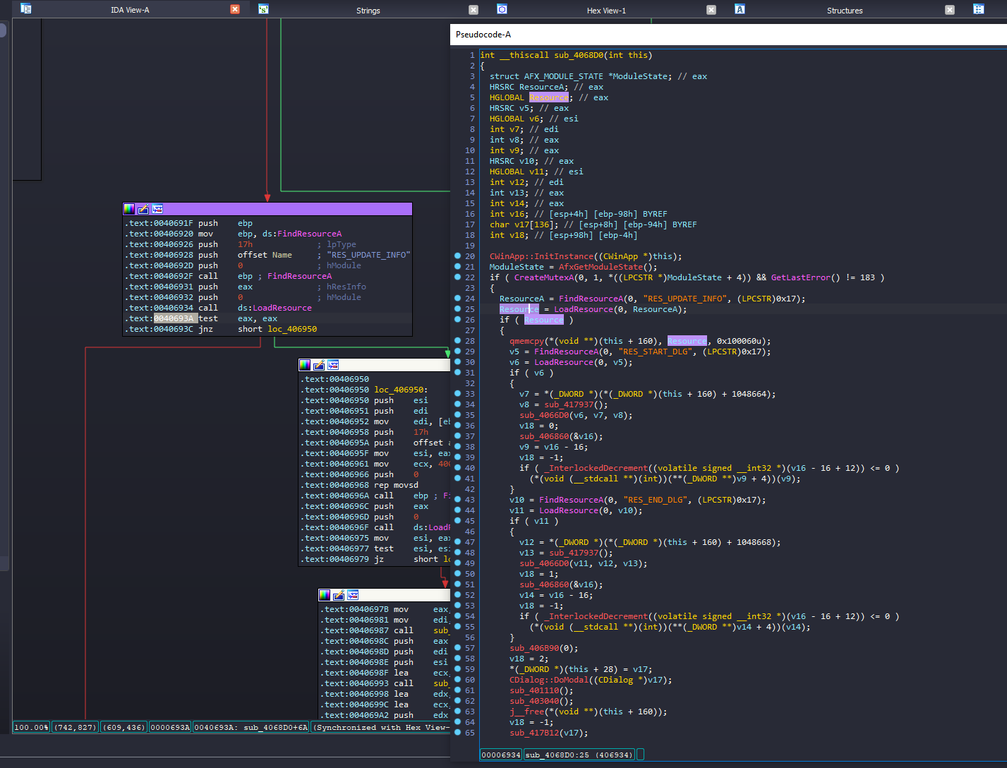
We know where the data is loaded by the application, so now we need to see how it's used. Doing static analysis from this point may be more work than it's worth if the data isn't operated on immediately. To speed things up I'm going to use a debugger's assistance. I used WinDbg's Time Travel Debugging to record an execution trace of the updater while it updates my radio. TTD is an invaluable tool and I'd highly recommend using it when possible. rr is an alternative for non-Windows platforms.
The decompiler output shows this function copies the RES_UPDATE_INFO resource to a dynamically allocated buffer. The qmemcpy() is inlined and represented by a rep movsd instruction in the disassembly, so we need to break at this instruction and examine the edi register's (destination address) value. I set a breakpoint by typing bp 0x406968 in the command window, allow the application to continue running, and when it breaks we can see the edi register value is 0x2be5020. We can now set a memory access breakpoint at this address using ba r4 0x2be5020 to break whenever this data is read.
Our breakpoint is hit at 0x4047DC -- back to the disassembler. In IDA you can press G and enter this address to jump to it. We're finally at what looks like the data processing function:
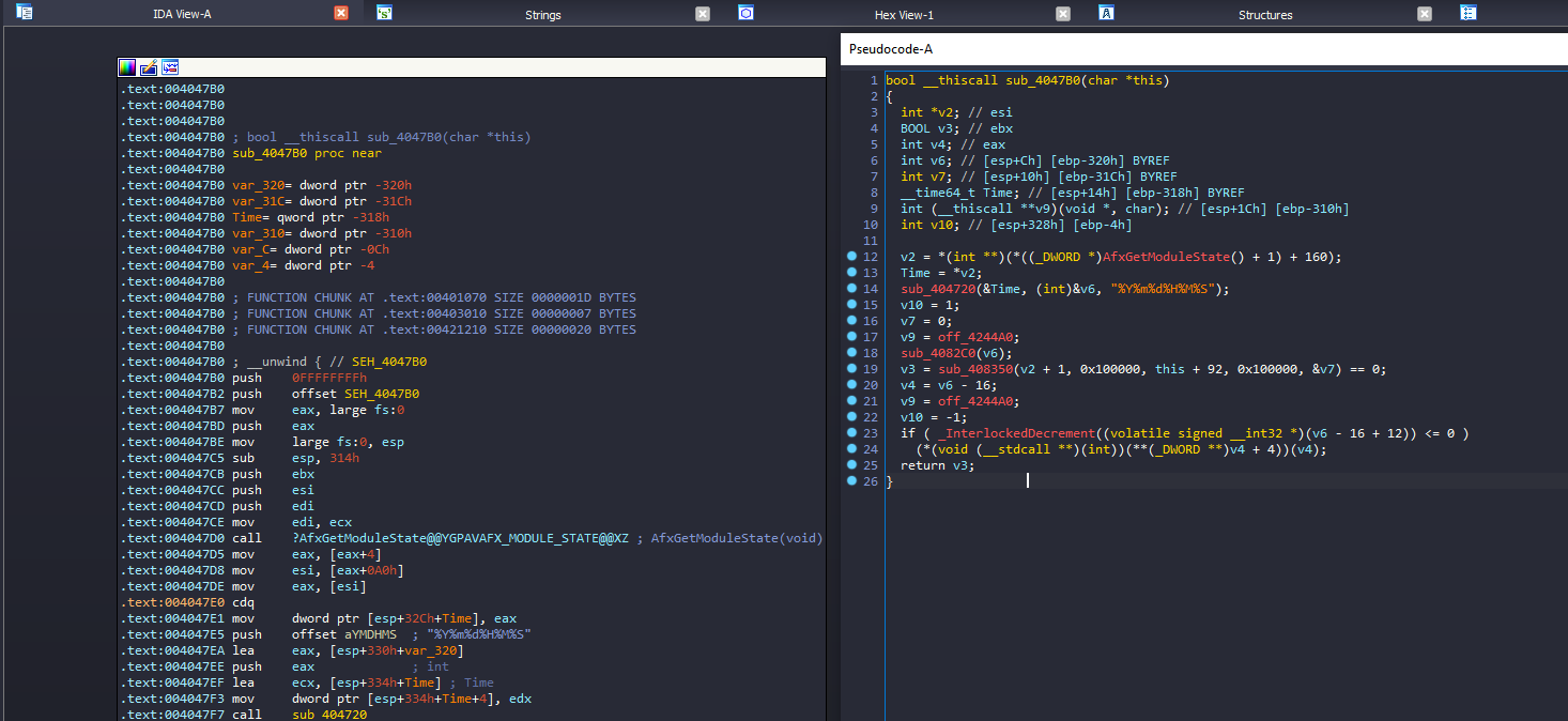
We broke when dereferencing v2 and IDA has automatically named the variable it's being assigned to as Time. The Time variable is passed to another function which formats it as a string with %Y%m%d%H%M%S. Let's clean up the variables to reflect what we know:
bool __thiscall sub_4047B0(char *this)
{
char *; // esi
; // ebx
char *; // eax
char *; // [esp+Ch] [ebp-320h] BYREF
int; // [esp+10h] [ebp-31Ch] BYREF
__time64_t; // [esp+14h] [ebp-318h] BYREF
int (**)(void *, char); // [esp+1Ch] [ebp-310h]
int; // [esp+328h] [ebp-4h]
// rename v2 to encrypted_data
= *(char **)(*((*)AfxGetModuleState() + 1) + 160);
= *(int *);
// rename this function and its 2nd parameter
format_timestamp(&, (int)&, "%Y%m%d%H%M%S");
= 1;
= 0;
=;
sub_4082C0();
= sub_408350(+ 4, 0x100000,+ 92, 0x100000, &) == 0;
=- 16;
=;
= -1;
if ( _InterlockedDecrement((volatile signed*)- 1) <= 0 )
(*(void (**)(char *))(**(**)+ 4))();
return;
}The timestamp string is passed to sub_4082c0 on line 20 and the remainder of the update image is passed to sub_408350 on line 21. I'm going to focus on sub_408350 since I only care about the firmware data right now and based on how this function is called I'd wager its signature is something like:
status_t sub_408350(uint8_t *input, size_t input_len, uint8_t *output, output_len, size_t *out_data_processed);Let's see what it does:
int __stdcall sub_408350(char *a1, int a2, int a3, int a4, _DWORD *a5)
{
int; // edx
int; // ebp
int; // esi
unsigned int; // ecx
char; // al
char *; // eax
int; // [esp+10h] [ebp-54h]
char v14[64]; // [esp+20h] [ebp-44h] BYREF
=;
= 0;
memset(, 0, sizeof());
if (<= 0 )
{
*=;
return 0;
}
else
{
while ( 1 )
{
=;
if (>= 8 )
= 8;
=-;
for (= 0;< 0x40;+= 8 )
{
= *;
v14[] = (unsigned)*>> 7;
v14[+ 1] = (& 0x40) != 0;
v14[+ 2] = (& 0x20) != 0;
v14[+ 3] = (& 0x10) != 0;
v14[+ 4] = (& 8) != 0;
v14[+ 5] = (& 4) != 0;
v14[+ 6] = (& 2) != 0;
v14[+ 7] =& 1;
++;
}
sub_407980(, 0);
if ()
break;
if (<= 0 )
goto;
=;
}
= &v14[1];
while ( 1 )
{
--;
if (>=)
return -101;
*(*)(+++) = v11[6] | (2
* (v11[5] | (2
* (v11[4] | (2
* (v11[3] | (2
* (v11[2] | (2
* (v11[1] | (2
* (*| (2 * *(- 1))))))))))))));
+= 8;
if ( !)
goto;
}
}
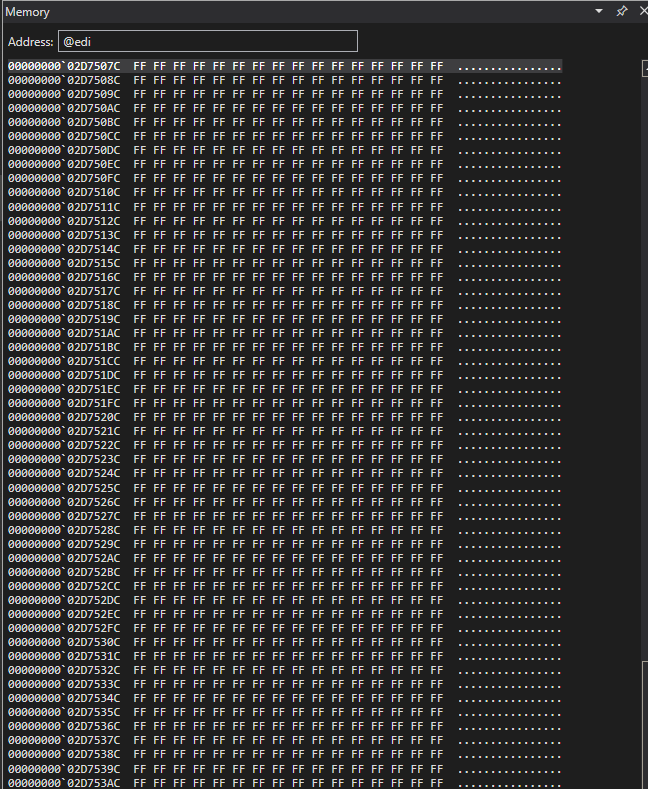
}I think we've found our function that starts decrypting the firmware! To confirm, we want to see what the output parameter's data looks like before and after this function is called. I set a breakpoint in the debugger at the address where it's called (bp 0x404842) and put the value of the edi register (0x2d7507c) in WinDbg's memory window.
Here's the data before:
After stepping over the function call:
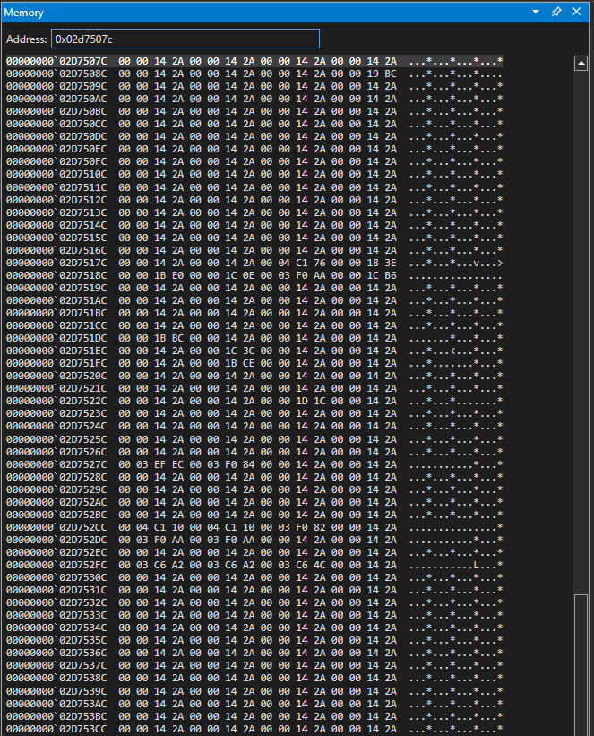
We can dump this data to a file using the following command:
.writemem C:\users\lander\documents\maybe_deobfuscated.bin 0x2d7507c L100000010 Editor has a built-in strings utility (Search > Find Strings...) and if we scroll down a bit in the results, we have real strings that appear in my radio!
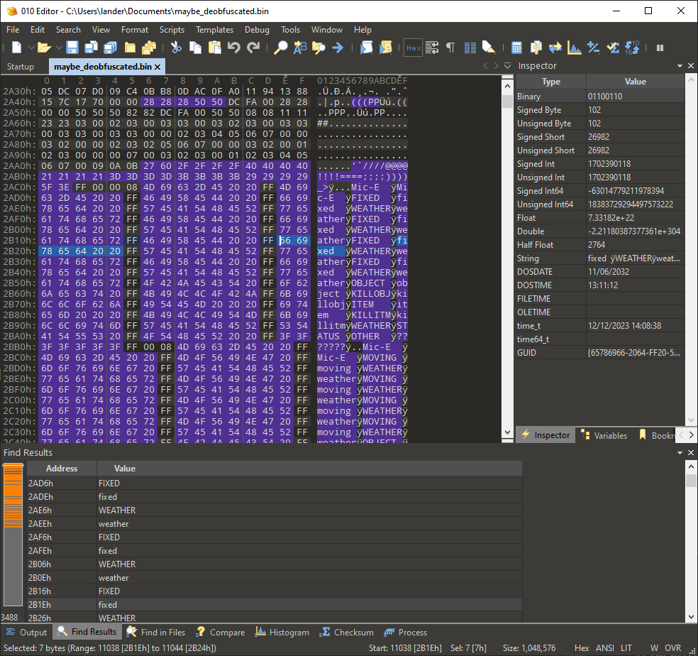
At this point if we were just interested in getting the plaintext firmware we could stop messing with the binary and load the firmware into IDA Pro... but I want to know how this encryption works.
# Encryption Details
Just to recap from the last section:
- We've identified our data processing routine (let's call this function
decrypt_update_info). - We know that the first 4 bytes of the update data are a Unix timestamp that's formatted as a string and used for an unknown purpose.
- We know which function begins decrypting our firmware image.
# Data Decryption
Let's look at the firmware image decryption routine with some renamed variables:
int __thiscall decrypt_data(
void *this,
char *encrypted_data,
int encrypted_data_len,
char *output_data,
int output_data_len,
_DWORD *bytes_written)
{
int; // edx
int; // ebp
int; // esi
unsigned int; // ecx
char; // al
char *; // eax
int; // [esp+10h] [ebp-54h]
char inflated_data[64]; // [esp+20h] [ebp-44h] BYREF
=;
= 0;
memset(, 0, sizeof());
if (<= 0 )
{
*=;
return 0;
}
else
{
while ( 1 )
{
=;
if (>= 8 )
= 8;
=-;
// inflate 1 byte of input data to 8 bytes of its bit representation
for (= 0;< 0x40;+= 8 )
{
= *;
inflated_data[] = (unsigned)*>> 7;
inflated_data[+ 1] = (& 0x40) != 0;
inflated_data[+ 2] = (& 0x20) != 0;
inflated_data[+ 3] = (& 0x10) != 0;
inflated_data[+ 4] = (& 8) != 0;
inflated_data[+ 5] = (& 4) != 0;
inflated_data[+ 6] = (& 2) != 0;
inflated_data[+ 7] =& 1;
++;
}
// do something with the inflated data
sub_407980(,, 0);
if ()
break;
if (<= 0 )
goto;
=;
}
// deflate the data back to bytes
= &inflated_data[1];
while ( 1 )
{
--;
if (>=)
return -101;
output_data[++] = idata[6] | (2
* (idata[5] | (2
* (idata[4] | (2
* (idata[3] | (2
* (idata[2] | (2
* (idata[1] | (2 * (*| (2 * *(- 1))))))))))))));
+= 8;
if ( !)
goto;
}
}
}At a high level this routine:
- Allocates a 64-byte scratch buffer
- Checks if there's any data to process. If not, set the output variable
out_data_processedto the number of bytes processed and return 0x0 (STATUS_SUCCESS) - Loop over the input data in 8-byte chunks and inflate each byte to its bit representation.
- After the 8-byte chunk is inflated, call
sub_407980with the scratch buffer and0as arguments. - Loop over the scratch buffer and reassemble 8 sequential bits as 1 byte, then set the byte at the appropriate index in the output buffer.
Lots going on here, but let's take a look at step #3. If we take the bytes 0xAA and 0x77 which have bit representations of 0b1010_1010 and 0b0111_1111 respectively and inflate them to a 16-byte array using the algorithm above, we end up with:
| 0 | 1 | 2 | 3 | 4 | 5 | 6 | 7 |    | 8 | 9 | A | B | C | D | E | F |
|---|---|---|---|---|---|---|---|----|---|---|---|---|---|---|---|---|
| 1 | 0 | 1 | 0 | 1 | 0 | 1 | 0 |    | 0 | 1 | 1 | 1 | 0 | 1 | 1 | 1 |
This routine does this process over 8 bytes at a time and completely fills the 64-byte scratch buffer with 1s and 0s just like the table above.
Now let's look at step #4 and see what's going on in sub_407980:
_BYTE *__thiscall sub_407980(void *this, _BYTE *a2, int a3)
{
// long list of stack vars removed for clarity
= (int);
= 15;
=;
v32[0] = (int);
= 0;
= 15;
do
{
for (= 0;< 48; *((*)&++ 3) =)
{
=;
if ( !)
=;
= *(*)(+ 48 *++ 4) ^ a2[(unsigned)byte_424E50[] + 31];
=;
*(&+) =;
if ( !)
=;
= *(*)(+ 48 *++ 5) ^ a2[(unsigned)byte_424E51[] + 31];
=;
*(&+) =;
if ( !)
=;
= *(*)(+ 48 *++ 6) ^ a2[(unsigned)byte_424E52[] + 31];
=;
*(&+) =;
if ( !)
=;
= *(*)(+ 48 *++ 7) ^ a2[(unsigned)byte_424E53[] + 31];
=;
v38[- 1] =;
if ( !)
=;
= *(*)(+ 48 *++ 8) ^ a2[(unsigned)byte_424E54[] + 31];
=;
v38[] =;
if ( !)
=;
= *(*)(+ 48 *++ 9) ^ a2[(unsigned)byte_424E55[] + 31];
+= 6;
}
v32[1] = *(int *)((char *)&
+ (((unsigned)v38[0] + 2) | (32 *+ 2) | (16 * (unsigned)v38[1] + 2) | (8 *+ 2) | (4 *+ 2) | (2 *+ 2)));
v32[2] = *(int *)((char *)&
+ (((unsigned)v38[6] + 2) | (32 * (unsigned)v38[2] + 2) | (16
* (unsigned)v38[7]
+ 2) | (8
* (unsigned)v38[3]
+ 2) | (4 * (unsigned)v38[4] + 2) | (2 * (unsigned)v38[5] + 2)));
v32[3] = *(int *)((char *)&
+ (((unsigned)v38[12] + 2) | (32 * (unsigned)v38[8] + 2) | (16
* (unsigned)v38[13]
+ 2) | (8 * (unsigned)v38[9]
+ 2) | (4 * (unsigned)v38[10] + 2) | (2 * (unsigned)v38[11] + 2)));
v32[4] = *(int *)((char *)&
+ (((unsigned)v38[18] + 2) | (32 * (unsigned)v38[14] + 2) | (16
* (unsigned)v38[19]
+ 2) | (8 * (unsigned)v38[15] + 2) | (4 * (unsigned)v38[16] + 2) | (2 * (unsigned)v38[17] + 2)));
v32[5] = *(int *)((char *)&
+ (((unsigned)v38[24] + 2) | (32 * (unsigned)v38[20] + 2) | (16
* (unsigned)v38[25]
+ 2) | (8 * (unsigned)v38[21] + 2) | (4 * (unsigned)v38[22] + 2) | (2 * (unsigned)v38[23] + 2)));
v32[6] = *(int *)((char *)&
+ (((unsigned)v38[30] + 2) | (32 * (unsigned)v38[26] + 2) | (16
* (unsigned)v38[31]
+ 2) | (8 * (unsigned)v38[27] + 2) | (4 * (unsigned)v38[28] + 2) | (2 * (unsigned)v38[29] + 2)));
v32[7] = *(int *)((char *)&
+ (((unsigned)v38[36] + 2) | (32 * (unsigned)v38[32] + 2) | (16
* (unsigned)v38[37]
+ 2) | (8 * (unsigned)v38[33] + 2) | (4 * (unsigned)v38[34] + 2) | (2 * (unsigned)v38[35] + 2)));
= (char *)(&- (*));
= &- (*);
= *(int *)((char *)&
+ (((unsigned)v38[42] + 2) | (32 * (unsigned)v38[38] + 2) | (16
* (unsigned)v38[43]
+ 2) | (8
* (unsigned)v38[39]
+ 2) | (4 * (unsigned)v38[40] + 2) | (2 * (unsigned)v38[41] + 2)));
=;
if (<= 0 )
{
= 8;
do
{
*^= *((*)+ (unsigned)result[] + 3);
result[1] ^= *((*)+ (unsigned)v19[()] + 3);
result[2] ^= *((*)+ (unsigned)result[&- (*)] + 3);
result[3] ^= *((*)+ (unsigned)result[-] + 3);
+= 4;
--;
}
while ();
}
else
{
= 8;
do
{
= result[32];
= *^ *((*)+ (unsigned)result[] + 3);
+= 4;
result[28] =;
*(- 4) =;
= result[29];
result[29] = *(- 3) ^ *((*)+ (unsigned)result[()- 4] + 3);
*(- 3) =;
= result[30];
result[30] = *(- 2) ^ *((*)+ (unsigned)result[&- (*)- 4] + 3);
*(- 2) =;
= result[31];
result[31] = *(- 1) ^ *((*)+ (unsigned)result[-- 4] + 3);
*(- 1) =;
--;
}
while ();
}
=;
= v32[0];
=- 1;
=- 1 <= -1;
++;
--;
}
while ( !);
return;
}Oof. This is substantially more complicated but looks like the meat of the decryption algorithm. We'll refer to this function, sub_407980, as decrypt_data from here on out. We can see what may be an immediate roadblock: this function takes in a C++ this pointer (line 5) and performs bitwise operations on one of its members (line 18, 23, etc.). For now let's call this class member key and come back to it later.
This function is the perfect example of decompilers emitting less than ideal code as a result of compiler optimizations/code reordering. For me, TTD was essential for following how data flows through this function. It took a few hours of banging my head against IDA and WinDbg to understand, but this function can be broken up into 3 high-level phases:
- Building a 48-byte buffer containing our key material XOR'd with data from a static table.
int v33;
unsigned __int8 v34; // [esp+44h] [ebp-34h]
unsigned __int8 v35; // [esp+45h] [ebp-33h]
unsigned __int8 v36; // [esp+46h] [ebp-32h]
unsigned __int8 v37; // [esp+47h] [ebp-31h]
char v38[44]; // [esp+48h] [ebp-30h]
v3 = (int)this;
v4 = 15;
v5 = a3;
v32[0] = (int)this;
v28 = 0;
v31 = 15;
do
{
// The end statement of this loop is strange -- it's writing a byte somewhere? come back
// to this later
for (= 0;< 48; *((*)&++ 3) =)
{
// v28 Starts at 0 but is incremented by 1 during each iteration of the outer `while` loop
=;
// v5 is our last argument which was 0
if ( !)
// overwrite v7 with v4, which begins at 15 but is decremented by 1 during each iteration
// of the outer `while` loop
=;
// left-hand side of the xor, *(_BYTE *)(i + 48 * v7 + v3 + 4)
// v3 in this context is our `this` pointer + 4, giving us *(_BYTE *)(i + (48 * v7) + this->maybe_key)
// so the left-hand side of the xor is likely indexing into our key material:
// this->maybe_key[i + 48 * loop_multiplier]
//
// right-hand side of the xor, a2[(unsigned __int8)byte_424E50[i] + 31]
// a2 is our input encrypted data, and byte_424E50 is some static data
//
// this full statement can be rewritten as:
// v8 = this->maybe_key[i + 48 * loop_multiplier] ^ encrypted_data[byte_424E50[i] + 31]
= *(*)(+ 48 *++ 4) ^ a2[(unsigned)byte_424E50[] + 31];
=;
// write the result of `key_data ^ input_data` to a scratch buffer (v34)
// v34 looks to be declared as the wrong type. v33 is actually a 52-byte buffer
*(&+) =;
// repeat the above 5 more times
if ( !)
=;
= *(*)(+ 48 *++ 5) ^ a2[(unsigned)byte_424E51[] + 31];
=;
*(&+) =;
// snip
// v18 gets written to the scratch buffer at the end of the loop...
= *(*)(+ 48 *++ 9) ^ a2[(unsigned)byte_424E55[] + 31];
// this was probably the *real* last statement of the for-loop
// i.e. for (int i = 0; i < 48; i += 6)
+= 6;
}- Build a 32-byte buffer containing data from an 0x800-byte static table, with indexes into this table originating from indices built from the buffer in step #1. Combine this 32-byte buffer with the 48-byte buffer in step #1.
    // dword_424E80 -- some static data
    // (unsigned __int8)v38[0] + 2) -- the original decompiler output has this wrong.
    //     v33 should be a 52-byte buffer which consumes v38, so v38 is actually data set up in
    //     the loop above.
    // (32 * v34 + 2) -- v34 should be some data from the above loop as well. This looks like
    //     a binary shift optimization
    // repeat with different multipliers...
    //
    // This can be simplified as:
    //     size_t index  = ((v34 << 5) + 2)
    //                     | ((v37[1] << 4) + 2)
    //                     | ((v35 << 3) + 2)
    //                     | ((v36 << 2) + 2)
    //                     | ((v37 << 1) + 2)
    //                     | v38[0]
    //     v32[1] = *(int*)(((char*)&dword_424e80)[index])
    v32[1] = *(int *)((char *)&dword_424E80
                    + (((unsigned __int8)v38[0] + 2) | (32 * v34 + 2) | (16 * (unsigned __int8)v38[1] + 2) | (8 * v35 + 2) | (4 * v36 + 2) | (2 * v37 + 2)));
    // repeat 7 times. each time the reference to dword_424e80 is shifted forward by 0x100.
    // note: if you do the math, the next line uses dword_424e80[64]. We shift by 0x100 instead of
// 64 because is misleading because dword_424e80 is declared as an int array -- not a char array.- Iterate over the next 8 bytes of the output buffer. For each byte index of the output buffer, index into yet another static 32-byte buffer and use that as the index into the table from step #2. XOR this value with the value at the current index of the output buffer.
// Not really sure why this calculation works like this. It ends up just being `unk_425681`'s address
// when it's used.
v19 = (char *)(&unk_425681 - (_UNKNOWN *)a2);
v20 = &unk_425680 - (_UNKNOWN *)a2;
// v4 is a number that's decremented on every iteration -- possibly bytes remaining?
if ( v4 <= 0 )
{
// Loop over 8 bytes
= 8;
do
{
// Start XORing the output bytes with some of the data generated in step 2.
//
// Cheating here and doing the "draw the rest of the owl", but if you observe that
// we use `unk_425680` (v20), `unk_425681` (v19), `unk_425682`, and byte_425683, the
// the decompiler generated suboptimal code. We can simplify to be relative to just
// `unk_425680`
//
// *result ^= step2_bytes[unk_425680[output_index] - 1]
*^= *((*)+ (unsigned)result[] + 3);
// result[1] ^= step2_bytes[unk_425680[output_index] + 1]
result[1] ^= *((*)+ (unsigned)v19[()] + 3);
// result[2] ^= step2_bytes[unk_425680[output_index] + 2]
result[2] ^= *((*)+ (unsigned)result[&- (*)] + 3);
// result[3] ^= step2_bytes[unk_425680[output_index] + 3]
result[3] ^= *((*)+ (unsigned)result[-] + 3);
// Move our our pointer to the output buffer forward by 4 bytes
+= 4;
--;
}
while ();
}
else
{
// loop over 8 bytes
= 8;
do
{
// grab the byte at 0x20, we're swapping this later
= result[32];
// v22 = *result ^ step2_bytes[unk_425680[output_index] - 1]
= *^ *((*)+ (unsigned)result[] + 3);
// I'm not sure why the output buffer pointer is incremented here, but
// this really makes the code ugly
+= 4;
// Write the byte generated above to offset 0x1c
result[28] =;
// Write the byte at 0x20 to offset 0
*(- 4) =;
// rinse, repeat with slightly different offsets each time...
= result[29];
result[29] = *(- 3) ^ *((*)+ (unsigned)result[()- 4] + 3);
*(- 3) =;
= result[30];
result[30] = *(- 2) ^ *((*)+ (unsigned)result[&- (*)- 4] + 3);
*(- 2) =;
= result[31];
result[31] = *(- 1) ^ *((*)+ (unsigned)result[-- 4] + 3);
*(- 1) =;
--;
}
while ();
}The inner loop in the else branch above I think is kind of nasty, so here it is reimplemented in Rust:
for _ in 0..8 {
    // we swap the `first` index with the `second`
    for (first, second) in (0x1c..=0x1f).zip(0..4) {
        let original_byte_idx = first + output_offset + 4;

        let original_byte = outbuf[original_byte_idx];

        let constant = unk_425680[output_offset + second] as usize;

        let new_byte = outbuf[output_offset + second] ^ generated_bytes_from_step2[constant - 1];

        let new_idx = original_byte_idx;
        outbuf[new_idx] = new_byte;
        outbuf[output_offset + second] = original_byte;
    }

    output_offset += 4;
}
# Key Setup
We now need to figure out how our key is set up for usage in the decrypt_data function above. My approach here is to set a breakpoint at the first instruction to use the key data in decrypt_data, which happens to be xor bl, [ecx + esi + 4] at 0x4079d3. I know this is where we should break because in the decompiler output the left-hand side of the XOR operation, the key material, will be the second operand in the xor instruction. As a reminder, the decompiler shows the XOR as:
v8 = *(_BYTE *)(i + 48 * v7 + v3 + 4) ^ a2[(unsigned __int8)byte_424E50[i] + 31];The breakpoint is hit and the address we're loading from is 0x19f5c4. We can now lean on TTD to help us figure out where this data was last written. Set a 1-byte memory write breakpoint at this address using ba w1 0x19f5c4 and press the Go Back button. If you've never used TTD before, this operates exactly as Go would except backwards in the program's trace. In this case it will execute backward until either a breakpoint is hit, interrupt is generated, or we reach the start of the program.
Our memory write breakpoint gets triggered at 0x4078fb -- a function we haven't seen before. The callstack shows that it's called not terribly far from the decrypt_update_info routine!
set_key(we are here -- function is originally calledsub_407850)sub_4082c0decrypt_update_info
What's sub_4082c0?
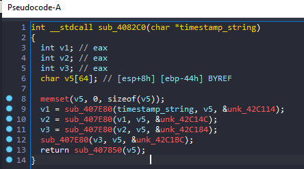
Not a lot to see here except the same function called 4 times, initially with the timestamp string as an argument in position 0, a 64-byte buffer, and bunch of function calls using the return value of the last as its input. The function our debugger just broke into takes only 1 argument, which is the 64-byte buffer used across all of these function calls. So what's going on in sub_407e80?
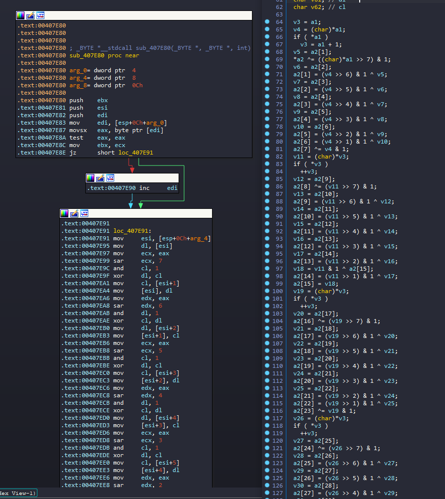
The bitwise operations that look supsiciously similar to the byte to bit inflation we saw above with the firmware data. After renaming things and performing some loop unrolling, things look like this:
// sub_407850
int inflate_timestamp(void *this, char *timestamp_str, char *output, uint8_t *key) {
for (size_t= 0;< 8;++) {
uint8_t= *;
if () {
+= 1;
}
for (int= 0;< 8;++) {
uint8_t= (>> (7 -)) & 1;
output[(* 8) +] ^=;
}
}
set_key(,);
decrypt_data(,, 1);
return;
}
// sub_4082c0
int set_key_to_timestamp(void *this, char *timestamp_str) {
uint8_t key_buf[64];
memset(&, 0, sizeof());
char *= inflate_timestamp(,, &, &);
= inflate_timestamp(,, &, &);
= inflate_timestamp(,, &, &);
inflate_timestamp(,, &, &);
set_key(, &);
}The only mystery now is the set_key routine:
int __thiscall set_key(char *this, const void *a2)
{
*; // ebp
char *; // edx
char; // al
char; // al
char; // al
char; // al
int; // eax
char v10[56]; // [esp+Ch] [ebp-3Ch] BYREF
qmemcpy(,, sizeof());
= &;
=+ 5;
do
{
= v10[0];
qmemcpy(, &v10[1], 0x1Bu);
v10[27] =;
= v10[28];
qmemcpy(&v10[28], &v10[29], 0x1Bu);
v10[55] =;
if ( *== 2 )
{
= v10[0];
qmemcpy(, &v10[1], 0x1Bu);
v10[27] =;
= v10[28];
qmemcpy(&v10[28], &v10[29], 0x1Bu);
v10[55] =;
}
for (= 0;< 48;+= 6 )
{
v3[- 1] = v10[(unsigned)byte_424E20[] - 1];
v3[] = v10[(unsigned)byte_424E21[] - 1];
v3[+ 1] = v10[(unsigned)byte_424E22[] - 1];
v3[+ 2] = v10[(unsigned)byte_424E23[] - 1];
v3[+ 3] = v10[(unsigned)byte_424E24[] - 1];
v3[+ 4] = v10[(unsigned)byte_424E25[] - 1];
}
++;
+= 48;
}
while ( (int)< (int));
return;
}This function is a bit more straightforward to reimplement:
void set_key(void *this, uint8_t *key) {
uint8_t scrambled_key[56];
memcpy(&,, sizeof());
for (size_t= 0;< 16;++) {
size_t= 1;
if (((uint32_t*))[] == 2) {
= 2;
}
for (int= 0;<;++) {
uint8_t= scrambled_key[0];
memcpy(&, &scrambled_key[1], 27);
scrambled_key[27] =;
= scrambled_key[28];
memcpy(&scrambled_key[28], &scrambled_key[29], 27);
scrambled_key[55] =;
}
for (size_t= 0;< 48;++) {
size_t= GLOBAL_KEY_SWAP_TABLE[] - 1;
size_t=+ (* 48);
this->key[] = scrambled_key[];
}
}
}# Putting Everything Together
- Update data is read from resources
- The first 4 bytes of the update data are a Unix timestamp
- The timestamp is formatted as a string, has each byte inflated to its bit representation, and decrypted using some static key material as the key. This is repeated 4 times with the output of the previous run used as an input to the next.
- The resulting data from step 3 is used as a key for decrypting data.
- The remainder of the firmware update image is inflated to its bit representation 8 bytes at a time and uses the dynamic key and 3 other unique static lookup tables to transform the inflated input data.
- The result from step 5 is deflated back into its byte representation.
My decryption utility which completely reimplements this magic in Rust can be found at https://github.com/landaire/porkchop.
# Loading the Firmware in IDA Pro
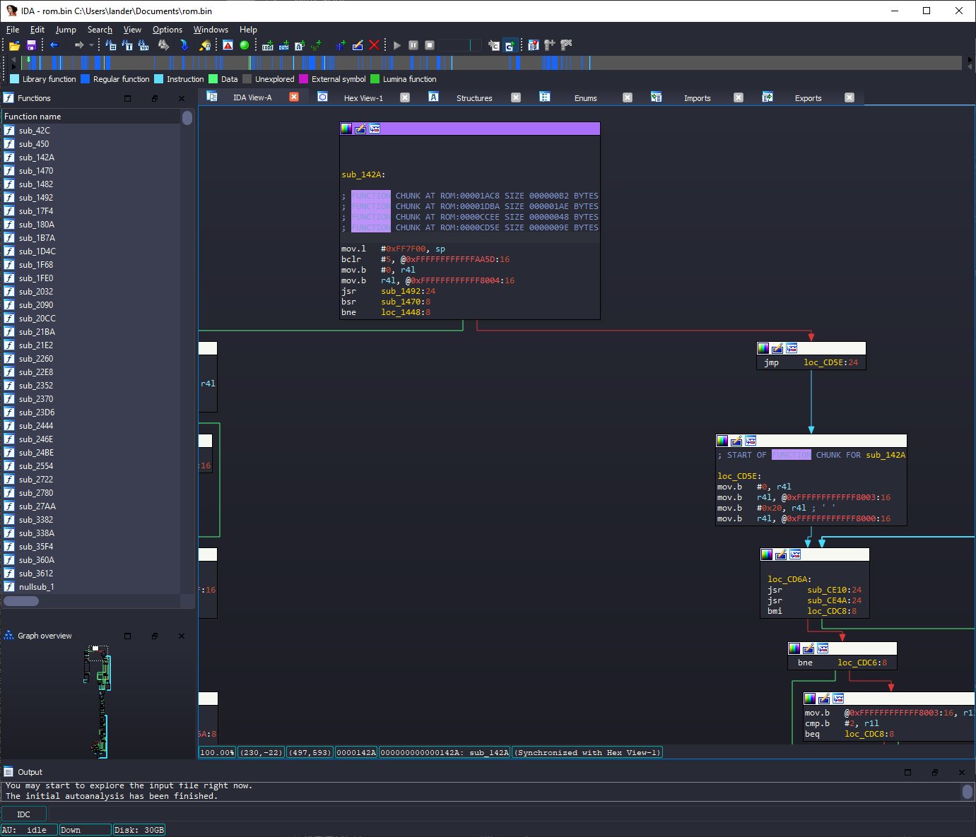
IDA thankfully supports disassembling the Hitachi/Rensas H8SX architecture. If we load our firmware into IDA and select the "Hitachi H8SX advanced" processsor type, use the default options for the "Disassembly memory organization" dialog, then finally choose "H8S/2215R" in the "Choose the device name" dialog...:

We don't have shit. I'm not an embedded systems expert, but my friend suggested that the first few DWORDs look like they may belong to a vector table. If we right-click address 0 and select "Double word 0x142A", we can click on the new variable unk_142A to go to its location. Press C at this location to define it as Code, then press P to create a function at this address:
We can now reverse engineer our firmware :)